
Choosing a tube bender in 2026 is about more than speed. A 3D CNC Automatic Tube Bending Machine must control feed, rotation, and bend angle while keeping the finished part within tolerance. On a production floor, small errors can become visible at the joint: a bracket sits crooked, or a tube no longer meets its fixture. That is why machine selection should begin with the actual parts, materials, and required output.
This guide examines three leading machine types and the features buyers should compare. Key checks include supported tube diameter and wall thickness, tooling changeover, programming options, bend repeatability, and service access. Ask for sample bends using your own material. Inspect the results, not just the brochure. A polished demonstration can still leave practical questions unanswered.
There is no universal winner. A compact cell may suit varied, low-volume work, while a high-output line may fit repeat production better. The right choice depends on part geometry, operator skills, floor space, and total ownership costs. Verify specifications with the manufacturer, and clarify what testing supports accuracy claims. Some details are easy to miss. Maintenance time, training, and tooling costs can reshape the decision after installation. A careful comparison helps identify the machine that fits real production needs—not merely the most impressive headline.
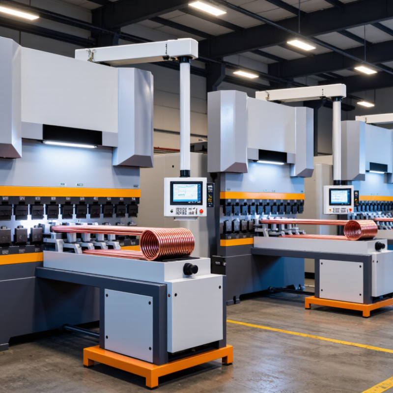
A 3D CNC automatic tube bending machine is a programmable system that forms straight tube into bends across multiple planes. Unlike a simple single-plane bender, it can rotate the tube between bends and position it for the next curve. The result may be a compact frame, exhaust line, handrail section, or fluid-routing assembly with bends in different directions. Stored programs guide the sequence, reducing the need to measure each bend by hand.
During a cycle, a feed axis advances the tube, a rotation axis sets its orientation, and a bending head forms each angle around a die. Depending on the tube and bend radius, tooling may include a clamp die, pressure die, or internal mandrel to limit flattening and wrinkles. CNC controls coordinate these movements and store repeatable settings. That matters. Consistent motion can reduce variation, but it cannot compensate for unsuitable tooling or poor material.
“Automatic” does not mean setup-free. An operator still checks tube diameter, wall thickness, material, bend radius, and springback, then inspects the first part against a drawing or gauge. Even small batch differences can shift a finished angle. A practical workflow includes a test bend, measurement, and program adjustment before production.
I would not trust a screen value alone; the tube itself has the final say.

A 3D CNC tube bender shapes a straight tube through controlled feeding, rotation, and bending. The operator loads a programmed sequence of bend angles, bend directions, and distances between bends. A feed axis advances the tube, while a rotary axis turns it to set the next plane. The bending head then forms each curve around a die.
Small details matter.
For example, a tube may move forward 120 millimeters, rotate 90 degrees, then receive a 45-degree bend. The CNC system coordinates these movements so bends land in the intended positions. Clamps hold the tube during forming, and tooling supports the required diameter and radius. Thin walls may wrinkle or flatten if the setup is unsuitable. Material type, wall thickness, and bend radius all affect the result.
Programming is only part of the work. Operators check the first formed piece against a drawing, using gauges or a measurement fixture to verify critical points. Metal can spring back after bending, so the programmed angle may need adjustment. In practice, the first setup is rarely perfect. That is normal, but each correction should be recorded and tested before production continues. A rushed measurement can repeat the same error across an entire batch.
In 2026, a top 3D CNC automatic tube bending machine is defined by more than its maximum bending speed. Look for coordinated control of feed, rotation, and bending axes, especially when a part needs bends in several planes. Accurate synchronization helps keep bend locations consistent and reduces twisting between operations. Still, published accuracy figures mean little without knowing the tube material, diameter, and wall thickness used during testing.
A rigid frame and responsive servo drives support repeatable movement under load. For tight-radius bends, compatible mandrels and wiper dies can help limit wrinkles and flattening. Tooling matters. A machine may offer many programmed axes, yet struggle if its tooling range does not match the job. Ask whether programs can be stored, edited, and recalled at the machine, and whether simulation flags collisions before production begins. That detail saves real setup time.
Useful monitoring features include bend-force feedback, alarms, and clear records of completed cycles. These help operators spot drift before a full batch is affected. But sensors do not replace inspection. Check sample parts with suitable gauges, particularly after a material or tooling change. Changeover time, operator training, and access to service support also affect daily output. In practice, teams sometimes overvalue top speed and overlook setup effort. That is easy to miss. Compare machines using your own part drawings and a representative production trial.
Representative CNC tube-bender configurations by independently controlled motion axes
More controlled axes can enable additional coordinated movements, such as tube feeding, rotation, bending, and handling. These are representative configurations, not a ranking or universal specification; actual axis counts and capabilities vary by machine.
2026 Top 3D CNC Automatic Tube Bending Machines?
Comparing Three Leading 3D CNC Tube Bending Machines
Choosing a 3D CNC tube bender means balancing part complexity, production volume, and setup time. Since published specifications vary, this comparison focuses on three common machine configurations rather than unsupported model rankings.
A compact single-stack machine suits workshops producing varied parts in small batches. It uses less floor space and can handle frequent changeovers, though operators may need to plan tooling carefully. Setup matters. A multi-stack machine offers several tooling sets on one bending head. That can reduce tool changes on complex parts with different bend radii. Its advantages depend on accurate programming and compatible tube dimensions, so confirm both before buying.
A high-speed, automated cell pairs CNC bending with feeding and part handling equipment. It can support repeat production and reduce manual handling, but requires more space and integration work. Not always. Compare sample-part results, bend repeatability, supported materials, and service response—not cycle-speed claims alone. Ask suppliers to run your actual tube, with your target geometry, and inspect springback, surface marks, and dimensional consistency. One overlooked detail can spoil a promising comparison: the best fit depends on your parts and workflow.
| Comparison Dimension | Compact Single-Stack Configuration | Production Multi-Stack Configuration | Heavy-Duty Multi-Stack Configuration |
|---|---|---|---|
| Typical tube outside diameter range | Approximately 6–38 mm | Approximately 6–65 mm | Approximately 10–100 mm |
| Typical CNC axis configuration | About 5–7 controlled axes, depending on machine design | About 7–10 controlled axes, depending on machine design | About 8–12 controlled axes, depending on machine design |
| Bending tooling | Usually one tool stack; suited to parts with a consistent bend radius | Multiple tool stacks can support different bend radii or tooling setups in one part program | Multiple heavy-duty tool stacks; designed for larger tooling and demanding forming work |
| 3D part capability | Produces bends in different planes through programmed tube rotation and feed | Handles complex multi-plane parts and can reduce tool-change interruptions | Handles large, complex multi-plane parts, subject to machine envelope and tooling limits |
| Common applications | Small-diameter tubing, furniture components, appliance parts, and general fabrication | Automotive components, exhaust assemblies, heat exchangers, and repeat production parts | Large structural tubes, heavy vehicle components, industrial frames, and larger-diameter pipe or tube work |
| Automation options | Automatic feeding and tube rotation are common; loading is often manual or semi-automatic | May be integrated with automatic loaders, unloading systems, and production-line controls | May support automated material handling, specialized loaders, and integration with downstream processes |
| Key advantage | Smaller footprint and lower tooling complexity for simpler part families | Good balance of flexibility and production efficiency for varied part geometries | Higher capacity for larger tubes and demanding production requirements |
| Main consideration | Limited suitability for parts requiring many bend radii or large tube sizes | Requires more floor space, tooling investment, and setup planning than a compact configuration | Higher equipment, tooling, and installation requirements; capacity depends strongly on material and bend geometry |
| Best suited to | Workshops producing small-to-medium tube parts with relatively straightforward geometries | Manufacturers needing flexible, repeatable production across multiple part designs | Operations processing larger or heavier tubes where machine capacity is a primary requirement |
Specifications above are indicative ranges for common industrial machine configurations, not guaranteed specifications for individual machines. Actual capacity depends on material grade, wall thickness, bend radius, tooling, and machine design. Confirm application limits with the equipment supplier.
A “top” machine is the one that reliably makes your parts, not the one with the highest advertised speed. Start with your tube’s outside diameter, wall thickness, material, and tightest centerline radius. Then check whether the machine can form your most complex part in multiple planes without collisions. Bring actual drawings and sample tubes to a supplier for a trial. A bend that looks simple on screen may wrinkle, flatten, or clash with the tooling. Fit matters.
Match capacity to real production. Estimate daily part quantities, changeover frequency, and the time operators spend loading and checking tubes. The International Federation of Robotics’ World Robotics 2024 report recorded 541,302 industrial robot installations worldwide in 2023, reflecting broader investment in factory automation. That figure does not mean every tube line needs a robot. It does suggest that automation decisions should consider how bending connects with loading, inspection, and downstream assembly. Ask for cycle-time tests using your own parts, plus details on tooling changes, software, maintenance, and operator training. Check the footprint, too. A fast machine can still become a bottleneck if setup takes too long. I’d be cautious about choosing from brochure numbers alone; they rarely capture awkward parts or imperfect material batches.
© 2025 EXCELSIUS MEDICAL All rights reserved
Taiwan Office
2F., No. 18, Ln.31, Sec.1, Huandong Rd.,
Xinshi Dist., Tainan City 744, Taiwan, R.O.C.
German Office
Zeppelinstr. 4, Haus 3&4,
D-85399 Hallbergmoos, Germany
