Installing eyeball lights can sharpen a room’s atmosphere, highlight artwork, and improve task lighting without replacing the entire ceiling. However, the result depends on more than choosing an attractive trim. Ceiling depth, housing compatibility, wiring condition, beam angle, and insulation clearance all influence the finished installation. This guide explains How to Install Eyeball Lights in 2026? with practical steps and careful safety decisions.
The article follows the work from planning to final aiming. You will learn how to measure the ceiling opening, select a compatible recessed housing, prepare the circuit, and connect the fixture correctly. A voltage tester, wire connectors, a screwdriver, and eye protection are useful companions. Turn off the breaker, then test the wires. Never rely only on a wall switch. Local electrical requirements may differ, so a licensed electrician should handle uncertain wiring, new circuits, or crowded junction boxes. That judgment is part of professional Eyeball Light Installation.
Real projects rarely go perfectly. A cutout may be slightly oversized. An old ceiling may hide unexpected cables. I have found that rushing the layout creates uneven light and visible repair work later. Measure twice. Cut once. Still, measurements can be wrong. This guide points out common mistakes, including poor spacing, incompatible dimmers, loose connections, and excessive heat around insulation. It also explains how to test the light, adjust its direction, and review the room after dark. A careful installation should look clean, operate reliably, and remain serviceable years later.
Choose the eyeball-light type before cutting the ceiling. Fixed trims suit general illumination, while adjustable gimbals aim at artwork or work surfaces. New-construction housings use ceiling joists for support. Remodel housings clamp to finished drywall. Measure the ceiling cavity first. A small mistake can leave the housing tilted.
IC-rated fixtures are designed for direct contact with insulation. Non-IC fixtures generally require clearance from insulation, often three inches under NEC rules. Confirm the exact language in NFPA 70, 2026 edition, Article 410, because local adoption and amendments can differ.
IC rating does not automatically mean airtight. Check the housing label and installation instructions. Damp or wet locations require the correct environmental rating, especially near bathrooms or covered outdoor ceilings. Never rely on appearance alone.
The U.S. Department of Energy’s Solid-State Lighting reports identify LEDs as the dominant source in general illumination, but efficiency does not remove installation risks. ENERGY STAR’s residential lighting research also emphasizes proper controls and compatible dimmers. Before wiring, switch off the circuit and verify de-energization with a tester. Connect grounding conductors carefully, protect cables from sharp housing edges, and maintain required box accessibility. Test aiming, dimming, and heat clearance after installation. My checklist still needs improvement: I sometimes focus on beam direction before confirming insulation depth. That order should change. Local inspection remains essential.
Eyeball lights need a lighting plan, not just a hole in the ceiling. Mark each fixture 30–36 inches from the wall. This offset usually creates a useful grazing effect on artwork, cabinets, or textured surfaces. I measure from the finished wall, not the framing. That small detail prevents uneven spacing.
Beam angle changes the result. A 24-degree beam creates a tighter highlight, while a 40-degree beam spreads light across a wider wall area. Divide the ceiling height by the beam’s spread to estimate coverage. For an eight-foot ceiling, a 30-degree beam may cover roughly four feet across. Aim the trim toward the wall’s visual target, then adjust the eyeball after installation. Avoid pointing every light directly downward.
The U.S. Department of Energy reports that LED lighting can use at least 75% less energy and last up to 25 times longer than incandescent lighting. That supports efficient, adjustable installations. However, efficiency does not fix poor placement. I have seen attractive fixtures produce harsh scallops because the wall offset was guessed. It is worth testing one light first. Cutouts can be expensive to repair. Use a dimmer rated for the selected LED load, and confirm the housing’s insulation and clearance requirements before closing the ceiling. I still recheck beam angles after furniture arrives. Rooms rarely look like the drawing.
Design the circuit before cutting the ceiling. Eyeball lights use adjustable housings, but their circuit still needs careful planning. For a 120 V system, select either 15 A or 20 A overcurrent protection. A 15 A circuit commonly uses 14 AWG copper conductors. A 20 A circuit commonly requires 12 AWG copper conductors. Never place a 20 A breaker on 14 AWG wiring. That mistake can create dangerous overheating.
Calculate the total lighting load, including future fixtures and any nearby equipment. Keep the circuit within local electrical limits. Many jurisdictions require AFCI protection for residential lighting circuits. Damp or wet locations may also require GFCI protection. Some areas require both devices, depending on placement and circuit design. Confirm the current electrical code before installation. Code rules change. Your local inspection office or a qualified electrician can verify the details.
Tips: Turn off the breaker, then test every conductor with an approved tester. Label the circuit at the panel. Use listed, compatible housings and secure each junction connection. Keep wiring away from sharp metal edges and insulation conditions that conflict with the housing rating. I once underestimated ceiling access, and the final connection became awkward. Plan the cable route first. Do not work live. Recheck conductor size, grounding, box fill, and protection before closing the ceiling.
How to Install Eyeball Lights in 2026?
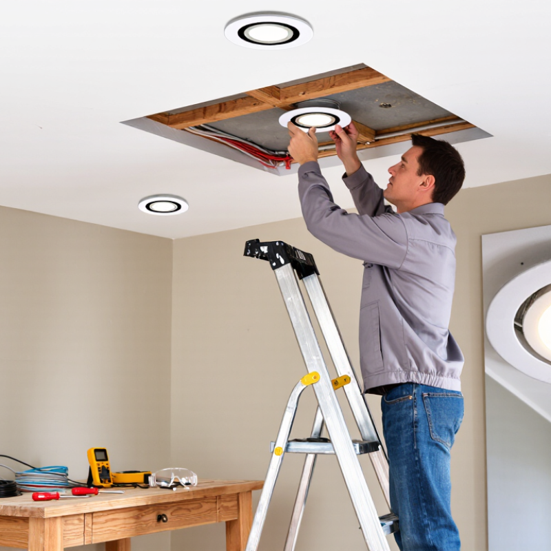
Eyeball lights need careful ceiling preparation, not just a quick cutout. Turn off the circuit at the breaker, then verify power with a reliable tester. Mark each location away from joists, pipes, and ductwork. Use a hole saw that matches the housing template. A loose opening can leave the trim uneven.
Choose IC-rated housings when insulation may touch the fixture. Confirm the housing is approved for the ceiling construction. Connect only 90°C-rated conductors where the installation instructions require them. These wires tolerate the heat produced inside recessed housings. Keep connections inside an accessible, approved junction box. Never bury a splice above the ceiling.
Tips
Measure twice. Cut once. Leave enough cable for a secure connection, but avoid loose loops near the lamp. Check the housing depth before cutting, especially beneath shallow roof spaces. My first layout would have looked better with wider spacing. Light coverage is easy to underestimate on paper. A mock-up with cardboard can reveal harsh shadows before permanent cutting.
After wiring, inspect every connection and install the trim without forcing it. Aim the eyeball direction after the lamps are operating. Look for flicker, heat, damaged insulation, or a breaker that trips. Stop if anything seems abnormal. Electrical rules and permit requirements vary by location, so have a qualified electrician review uncertain work. A final inspection may catch a crowded box, poor grounding, or conductors rated below the fixture’s temperature requirement.
| Step | Installation Phase | Task and Technical Requirement | Typical Planning Data | Verification and Safety Point |
|---|---|---|---|---|
| 1 | Plan the Layout | Mark the light locations and confirm that the adjustable eyeball beam will illuminate the intended wall, work surface, or display area. | Common spacing: approximately 900–1,500 mm between fixtures, depending on ceiling height and beam angle. | Avoid placing a fixture directly over joists, ducts, pipes, or other concealed services. |
| 2 | Turn Off Power | Switch off the circuit breaker before opening the ceiling or handling wiring. | Verify power is absent at the work area with a properly rated voltage tester. | Do not rely only on the wall switch. Lock out or label the breaker when practical. |
| 3 | Inspect the Ceiling Cavity | Check the available depth, insulation type, framing, ventilation paths, and existing electrical cables. | Typical recessed housing depth: approximately 90–150 mm, but the listed housing dimensions control. | Use an inspection opening or approved detection method before cutting a finished ceiling. |
| 4 | Select the Housing | Use an IC-rated housing when the luminaire is installed in direct contact with thermal insulation, provided the complete assembly is listed for that application. | IC-rated means the housing is designed for contact with insulation under its listing conditions. | Do not cover ventilation openings or install a non-IC housing against insulation. Follow the housing label and local code. |
| 5 | Mark the Cutout | Trace the supplied template or the exact aperture diameter specified for the housing or trim. | Common round apertures: approximately 100–150 mm; the required cutout is product-specific. | Do not use the visible trim diameter as the cutting dimension. Measure twice before cutting. |
| 6 | Cut the Ceiling | Cut a clean, round opening using a suitable hole saw or drywall tool while supporting the ceiling surface. | Keep the opening within the stated tolerance, commonly only a few millimeters around the specified diameter. | Stop immediately if the blade contacts a cable, pipe, duct, or structural member. |
| 7 | Prepare the Junction Box | Make all connections inside the listed junction box or wiring compartment using approved cable connectors and strain relief. | Leave enough conductor length for safe termination and future servicing, as required by local code. | Do not leave wire splices loose above the ceiling or outside an approved enclosure. |
| 8 | Connect the Conductors | Connect line, neutral, and equipment grounding conductors according to the luminaire wiring diagram. Use 90°C-rated conductors where required by the luminaire listing and applicable code. | Typical residential supply: 120 V AC; confirm the actual circuit voltage before connection. | Match conductor polarity, secure every terminal, and ensure the grounding connection is continuous. |
| 9 | Install the Housing | Place the housing through the ceiling opening and secure it with the supplied clips, brackets, or framing supports. | Housing must remain stable without compressing the ceiling material or damaging insulation. | Maintain all clearances stated on the housing label. IC-rated status does not override other installation restrictions. |
| 10 | Install the Eyeball Trim | Attach the adjustable eyeball trim or directional module after the housing and wiring are secure. | Typical adjustment range: approximately 20–40 degrees, depending on the trim design. | Make sure the trim is flush, fully retained, and able to move without rubbing against the ceiling opening. |
| 11 | Test the Circuit | Restore power and test the light, switch operation, dimming compatibility, and directional adjustment. | Typical LED recessed load: approximately 8–15 W per fixture, subject to the selected luminaire. | Turn power off again before correcting any wiring, flickering, overheating, or abnormal noise. |
| 12 | Final Inspection | Check the trim, housing, junction box, insulation position, conductor connections, and ceiling finish. | All components should remain accessible as required for maintenance and code compliance. | Obtain any required electrical inspection or permit approval before closing the project. |
Aim each eyeball light after the trim, lamp, and dimmer are fully installed. Start with a temporary test. Point the beam at artwork, a countertop, or a textured wall. Check glare from the usual standing position, not only from the ladder. A small adjustment can change the shadow line noticeably. Use a calibrated light meter when possible. The U.S. Department of Energy’s Solid-State Lighting reports identify efficacy above 100 lumens per watt as common in many LED products, but brightness alone does not prove good lighting.
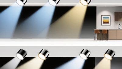
Select fixtures rated at least 80 CRI, then verify the actual specification sheet. For kitchens, galleries, and wood surfaces, compare samples under 2700–3000 K. Warm light can make white paint appear cream. IES TM-30 evaluates color fidelity and gamut through Rf and Rg, offering more detail than CRI alone. A CRI of 80 is only a starting point. I still find that two fixtures with similar ratings can render red fabrics differently.
Before closing the ceiling, confirm insulation-contact and damp-location ratings where required. Check housing depth, beam spacing, junction-box access, grounding, and local electrical rules. Some jurisdictions require AFCI or GFCI protection, especially in specific rooms. Record the fixture model, circuit, color temperature, and test results. Photograph the aiming angle. My first layout is rarely perfect. Recheck it at night, with furniture installed, because an empty room can hide glare and uneven brightness. (Sources: U.S. DOE Solid-State Lighting R&D reports; IES TM-30.)
© 2025 EXCELSIUS MEDICAL All rights reserved
Taiwan Office
2F., No. 18, Ln.31, Sec.1, Huandong Rd.,
Xinshi Dist., Tainan City 744, Taiwan, R.O.C.
German Office
Zeppelinstr. 4, Haus 3&4,
D-85399 Hallbergmoos, Germany